Going solar: a maintenance-free redesign of my plant watering indicator
If you want one of these indicators yourself then keep an eye on my store for the next revision which I will be putting up for sale in the next few months: https://hortus.dev/.
Introduction
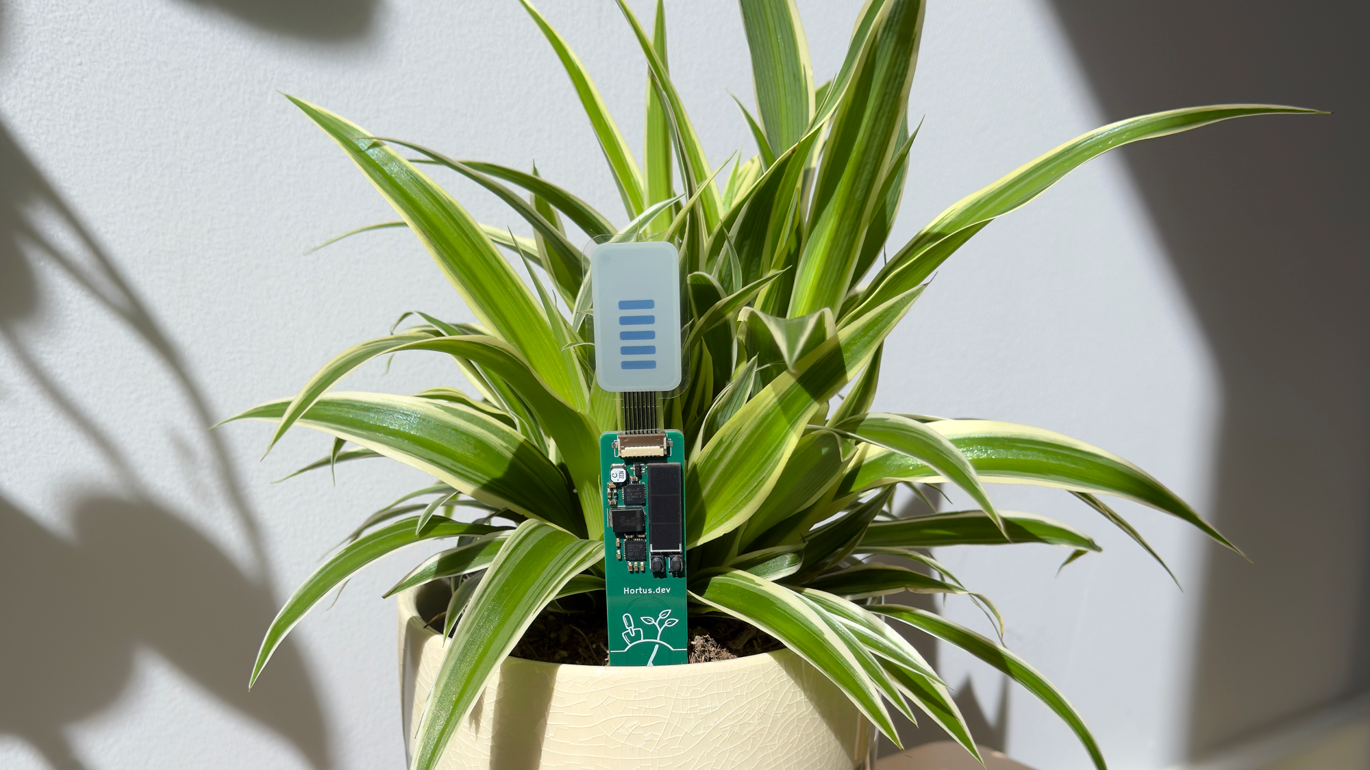
A while ago I built a coin-cell powered soil moisture sensor with a cool electrochromic bar chart display from a company called Ynvisible. It’s been quietly keeping my houseplants alive ever since. The only issue is that every time I look at it I think about the coin cell and how it will eventually run out. The ones I’ve built are still going strong on their first cells after a little over a year, and I estimate that they’ll last at least another year - but the prospect of that battery change doesn’t feel quite right to me, mainly because it generates some e-waste in the form of the spent cell even if that’s pretty minor in the grand scheme of things.
With this version I wanted to eliminate that waste. I did it by redesigning the monitor to use a tiny solar panel and energy harvesting chip that should enable it to run indefinitely on a window sill without ever needing any maintenance. I also took the opportunity to jazz up the art on the PCB and make it more compact so that it can be used with smaller pots, thus saving a wider range of plants from watering neglect.
What changed (and what didn’t)
This new version keeps the Ynvisible bar chart display, upgrades to a newer ultra low power STM32 chip, and makes use of the built in TSC capacitive touch peripheral rather than my previous DIY implementation to measure soil moisture more efficiently. The CR2032 coin cell is replaced with a small 110mAh LiPo which is charged using a tiny little 23x8 mm solar cell and an AEM10941 energy harvesting IC. I also reduced the overall size of the device so that it could fit in a wider variety of plant pots.
A note on the display
A quick aside on the Ynvisible display before getting into the rest of the design. When I built the original sensor, Ynvisible were selling the seven-segment bar graph display as samples in packs of three through their website which made it really easy to get hold of one to play with. They aren’t doing that any more - which is understandable, as selling displays as one-off samples through a webstore isn’t really what they’re set up to do - so for the new sensor I’m using their prototyping service to have a small run of these displays made. As a nice side effect this also opens the door to some custom display designs for future projects, which I’m pretty excited about.
The AEM10941
The AEM10941 is an energy harvesting IC purpose built for extracting minuscule amounts of power from small PV cells like the surface mount KXOB25-05X3F that I am using. It has a number of features that support this including maximum power point tracking (MPPT), cold start from extremely low power, and a highly configurable storage element that lets it work with a wide range of storage technologies like super capacitors and lithium based batteries. It takes care of things like under and over charge protection, has two built-in regulators with configurable output voltages, and exposes status pins so that the host MCU can check the state of the system. Basically it handles everything needed to reliably power a small device from a compact solar source.
On my board I have it configured to use the dual cell super capacitor scheme by default. This is because it has the largest available voltage range out of all the built-in configurations, enabling the regulators for as long as the energy store is between its maximum voltage of 4.5V and its minimum of 2.8V. Plugging those values into the equation E = ½ × C × (V_max² − V_min²) gives me a theoretical 9.31mJ of useable energy when it is fully charged. A measurement and display cycle takes about 3mJ so this should allow for three update cycles. In practice it didn’t turn out to be that good. I was using the output from the LDOs as soon as they became available which happened at the lower V_CHRDY voltage of 3.67V, and even then the tantalum polymer capacitor struggled to charge up that high in all but the brightest direct sunlight due to leakage currents. I found that it would generally only manage about one measurement cycle and often brown out halfway through the display update which wasn’t ideal.
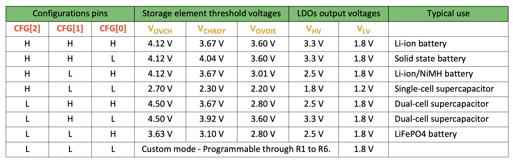 A table from the datasheet showing the built in energy storage configurations for the AEM10941
I exposed the configuration pins via solder jumpers on the back of the board, meaning that I could pick a different configuration that better suited the tantalum capacitor. The LiFePO4 battery configuration worked reasonably well, with a lower V_CHRDY value that had to be hit in order to switch on power to the MCU. The 0.3V swing gave me a theoretical 1.33mJ of energy to use per cycle. In order to make this work I tweaked the display code to only switch on/off one segment of the display at a time, sleeping for 5 minutes between each one to give the capacitor a chance to recover. This did work, but it wasn’t ideal as it took up to 35 minutes to show the correct reading on the display. While this is probably tolerable from a user experience perspective (realistically soil doesn’t go from fully wet to fully dry in under an hour, and people expect a certain amount of ‘soaking’ time after watering) it really didn’t play nicely when there wasn’t quite enough light to charge up between updates as the system would brown out and start the whole process of updating the display from the beginning again. I probably could have squeezed some more energy out by programming a custom configuration into the AEM10941, but I thought it better to accept that I was fighting physics and pick a more suitable energy storage medium.
Picking a new energy store
The first store that jumped to mind was a super-capacitor, and this is what I used with my initial proof of concept where I replaced the battery in my old moisture sensor with an AEM10941 breakout board (an AEMLion which I bought a while ago because I wanted to try the chip out) and a 1.5F supercap. It worked well enough to convince me that this project was worth pursuing, but with hindsight I realised that it still suffered from the same problems albeit to a lesser extent.
In the end I decided to bite the bullet and go with a LiPo battery. I picked a tiny little 110mAh pack which even by itself would easily run the whole system for over a year on a single charge. With the solar cell and energy harvester keeping it topped up it essentially becomes a massive energy buffer rather than a primary energy source, which lets me significantly reduce sleep times and make the whole sensor much more responsive.
This initially felt like a bit of a cop-out. Supercaps are mechanically robust, don’t really wear out in any meaningful way, and aesthetically feel like a much better fit for an indefinitely-powered solar device. But from a size, energy density, and cost perspective it’s a no brainer. To get anything close to the buffer capacity of even this tiny LiPo you’d need a stack of supercaps that would dwarf the rest of the board and cost many times more than every other component put together - and they’d still bleed energy through leakage currents that scale with capacity, just like the tantalum cap did at smaller scale.
The obvious downside is that a LiPo is a chemical battery and will eventually wear out, but in this configuration the cell should rarely move more than a percent or two from full charge. The load is tiny, the panel keeps it topped up, and the AEM10941 takes care of under and over voltage protection which are the things that tend to actually kill these cells. Shallow-cycled and buffered like this any wear should be far too slow to matter in practice.
Using the TSC peripheral
The other big change on the electronics side was moving to a newer STM32 (the STM32U031K6) and letting its built-in Touch Sensing Controller (TSC) handle the capacitive measurement that I’d previously rolled by hand. In the original design I was using a GPIO pin to slowly charge the sensing element through a resistor and timing how long it took to cross a voltage threshold on another pin. It worked, but it tied up the CPU for the duration of every measurement and the timing resolution was limited by how quickly I was willing to poll.
The TSC peripheral does essentially the same thing in hardware. It charges a sampling capacitor from the sensing electrode, counts how many charge transfers it takes to reach a reference threshold, and hands the result back as a number. During the acquisition the CPU sits in Sleep mode and is woken by the TSC’s end-of-acquisition interrupt - no busy-waiting and no software timing loop. In practice the measurements also come back faster and more consistently than my old polled approach managed.
A smaller, prettier board
The new board is significantly more compact. The old one was 140 × 75 mm - fine in a big pot but didn’t always fit in some smaller ones. The new one is 110 × 20 mm: a fair bit shorter, and much narrower. It’s now a slim enough strip that it slips in alongside the plant without taking over or displacing too much soil.
To make that tight layout actually fit, I switched from a 2-layer to a 4-layer board. I’ve tended to default to 2 layers in the past purely on cost, but JLCPCB’s pricing for small 4-layer runs has come down enough that the difference was genuinely minimal - well worth it for how much easier it made compact placement and routing on a narrow board.
Another small space win came from swapping the serial programming header off the old board for a Tag-Connect TC2030 footprint. The TC2030 is a pogo-pin connector that only needs a small pad pattern and a couple of locating holes on the board itself, with no permanent header taking up real estate. It also lets me program the chip over SWD which I’d called out as the ‘proper’ approach in the original writeup but didn’t have the hardware for at the time.
I also had a bit of fun with my logo on the silkscreen, with roots reaching down from underneath it past the max soil level line. The corners of the board outline are rounded off too, which makes the whole thing feel a lot more polished. Small touches, but satisfying ones.
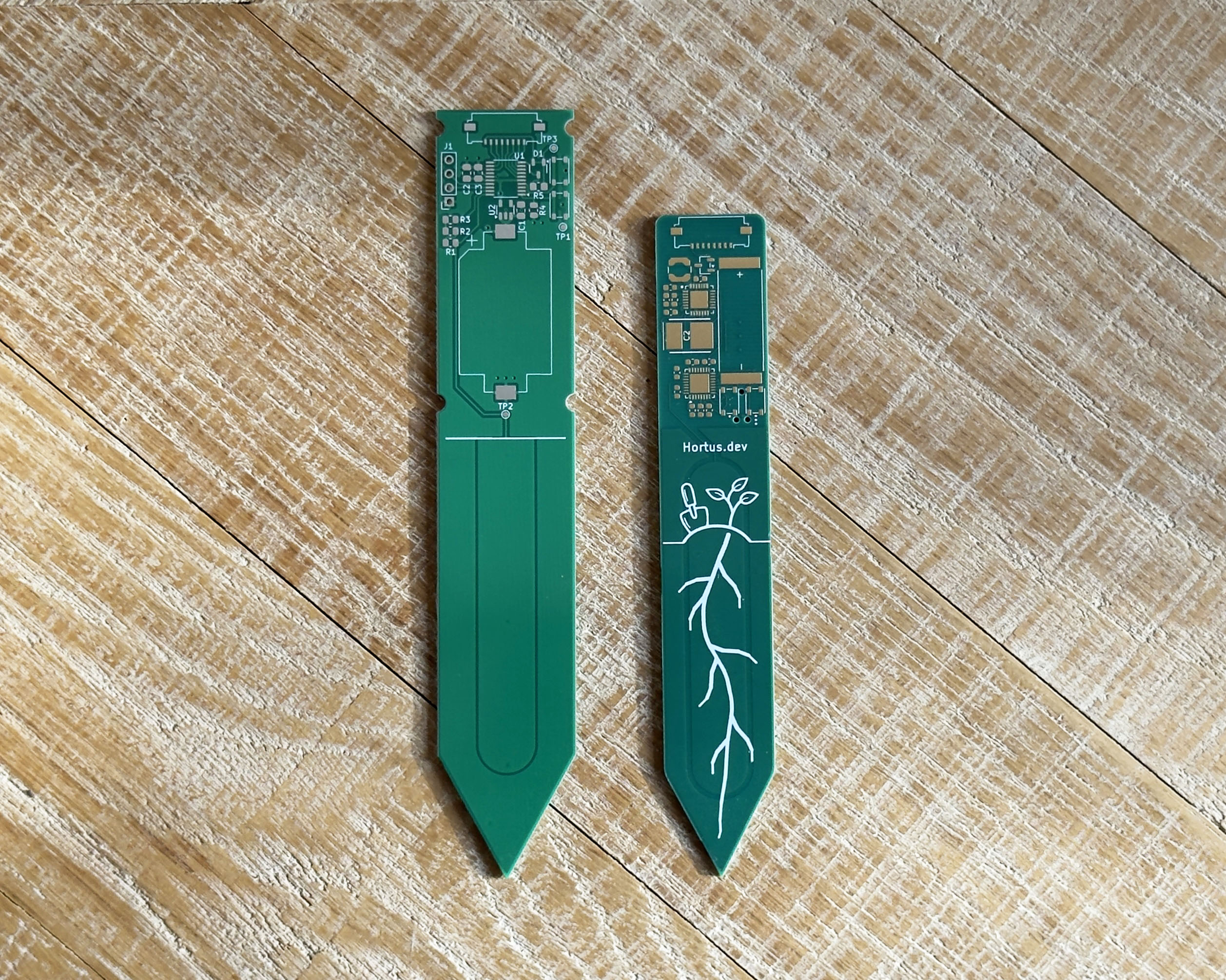 The new board (right) next to the original (left). The narrower form factor, rounded corners, and the new logo with roots reaching past the max soil level line are all visible.
On the windowsill
Once the new design was up and running I wanted a proper measurement of how much power it actually pulls. I hooked it up to my Nordic PPK2 and let it log for an hour while doing its normal thing - waking up periodically, taking a TSC measurement, refreshing the display, and dropping back into Stop 2.
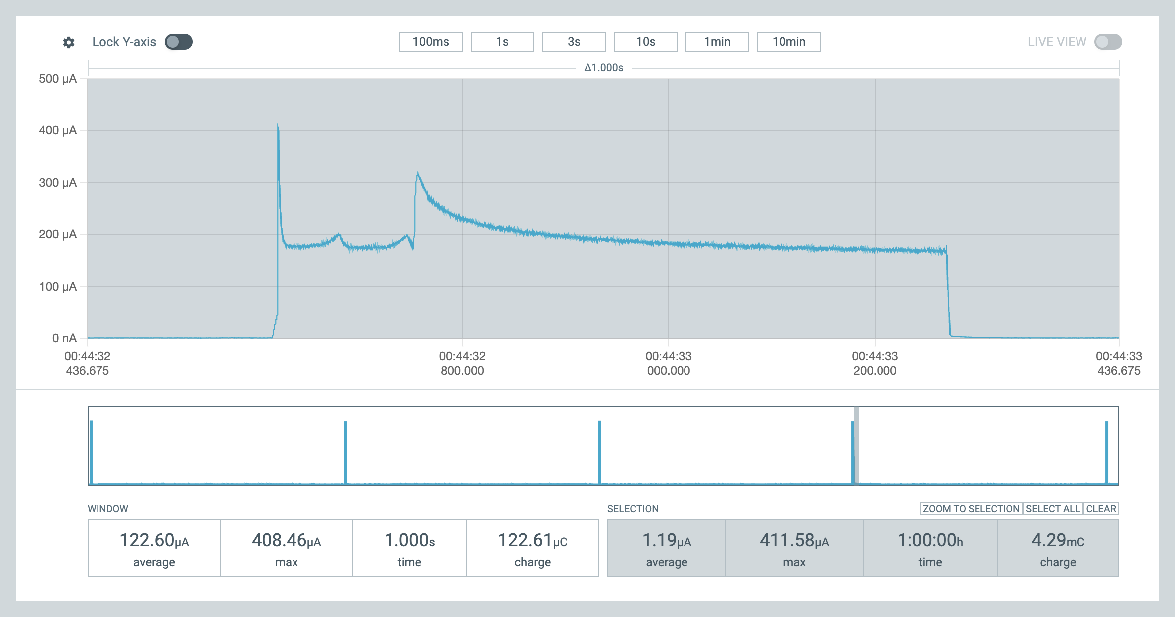 PPK2 capture: a single measurement and display refresh cycle in the main pane, with the full hour-long timeline and 1.2µA average shown in the strip below
The average came out at just 1.2µA - a combination of the TSC making each measurement cheaper than my old polled approach, and the STM32U0 having dramatically lower idle current than the L0 it replaces. To put that into perspective, the 110mAh LiPo on its own would take a little over ten years to run flat at that rate even with no solar input at all - long enough that self-discharge would empty it before the load did.
I haven’t had it running through a full winter yet so I can’t speak to how it copes with a string of long, dim days, but on paper I don’t really expect to see the LiPo voltage drop in any meaningful way. With the load averaging just 1.2µA, even an overcast windowsill at a few thousand lux of diffuse daylight should be enough to drive the KXOB25-05X3F solar cell to somewhere in the tens of microamps - already an order of magnitude more than the device needs - and direct sun lands you a couple of orders of magnitude beyond that. Realistically the LiPo just sits at full charge.
Wrapping up
I’m really pleased with how this has turned out. I now have a handful of them dotted around the house looking after plants and they really do help take the guesswork out of watering - they’re also quite discreet in practice, which is an important part of making something that doesn’t ruin the visual appeal of the plants they’re keeping alive. The AEM10941 + KXOB25 combination works really well and is something I’m definitely going to reach for again in future projects.
As with most of my projects I’m planning to put a small batch up for sale on the store, but I want to make a couple of revisions first. The main one is sorting out the battery: at the moment I’m bodging the LiPo’s leads onto test points which works fine but isn’t exactly elegant, so the next revision will have a proper space for the LiPo with dedicated pads to solder its leads to. I should probably also add a case to protect it. There’s also the lead time on the displays - these are being manufactured now and will take a little while to arrive, especially as I’m using the run as an opportunity to try out some custom designs. If you’d like one of these on your windowsill, keep an eye on my store, hortus.dev, over the next few months.
