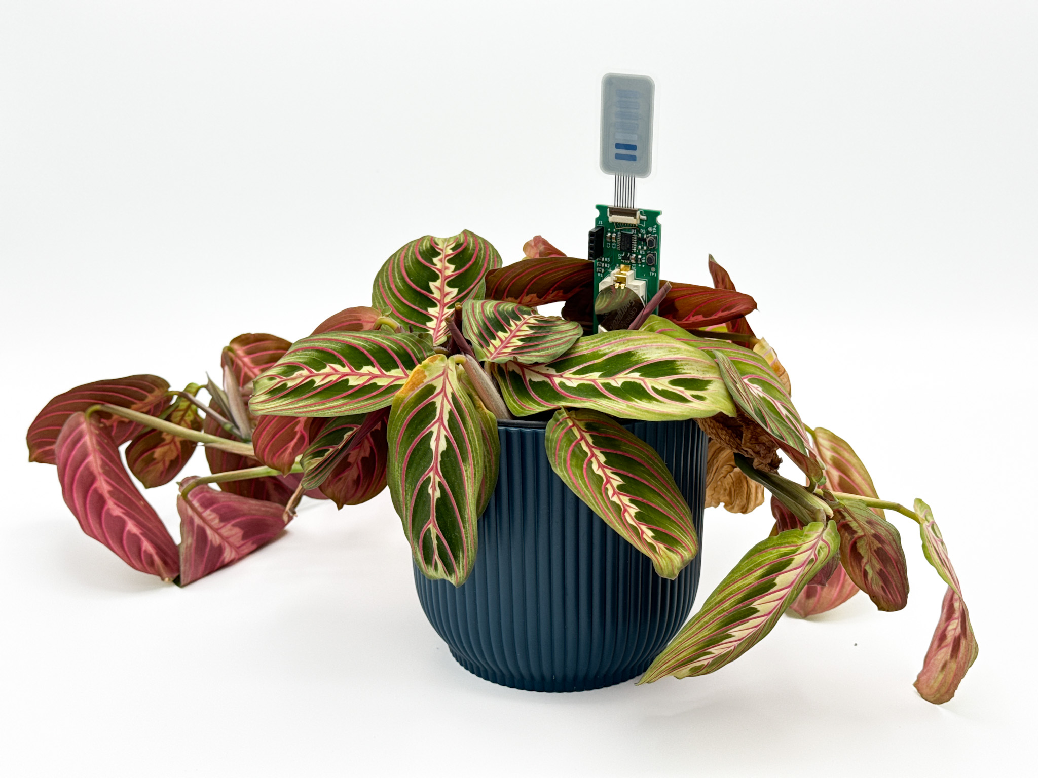
Designing an ultra low power plant watering indicator
If you want one of these indicators yourself then I have a few up for sale on my store: https://hortus.dev/products/houseplant-watering-sensor.
Introduction
I’ve always been a bit rubbish at looking after plants. I’m not a particularly organised person and all too often I forget to water them so they end up being in a near permanent state of drought. On occasions when I do remember to water them it will turn out that my (much more organised) wife has done it already and I end up overwatering which is apparently just as bad.
A project I’ve had on the back burner for a while now is an automated watering system. I’ve got started on this a few times, buying pumps and sensors, but for whatever reason I’ve never quite got around to finishing it. It’s not a particularly complicated project but it is one of those ones where it’s easy to get the dopamine hit from doing 90% of the work making something that kind of functions, and then lose interest in the last 10% needed properly complete it.
When I came across these bar graph displays by a company called Ynvisible I immediately thought about this project again. The thing that I found made automated watering a bit of a pain to manage was the watering part - you need a pump and a reservoir which are easy enough to use, but they take up a lot of space on a windowsill and need a decent amount of power to run. I just couldn’t see myself maintaining a set up like this long term which is why I lost interest. Thinking about it, the core problem I was trying to solve wasn’t watering the plants, it was knowing when to do it. If I have an indicator that lets me know when the soil is getting dry then I don’t mind having to use a watering can myself.
These displays seemed perfect for the job. They only need an occasional pulse to update/refresh the indicated level, and they require next to no power to do it. I really love the idea of low power projects with a long life - especially when there’s the prospect of them running for years on a simple coin cell. I bought some samples and fired up Kicad ready to start designing.
 Ynvisible’s seven segment bar graph display
How to measure moisture
There are a few ways to measure soil moisture but the most common (and accessible) ways are probably resistive and capacitive sensing. Resistive sensing is the most straight forward; you stick two bits of conductive material in the ground and measure the resistance between them. When the soil is wet, the water makes it easier to for current to flow between the two conductors, lowering the soils overall resistance. Sensors that work like this have the advantage of being really simple and cheap, but the disadvantage of being extremely inconsistent - especially given that they will degrade quite rapidly over time as the conductors corrode in damp soil.
Capacitive sensors avoid this by not needing conductors to be in direct contact with the soil. Instead they take advantage of the fact that water has quite a high relative permittivity compared to soil. Relative permittivity is a measure of how well a material can hold an electric field compared to a vacuum (i.e. nothing), the higher a material’s permittivity, the stronger the electric field it can support and thus the more charge it can store. In most capacitive sensors two large planes of copper are placed close to each other on a circuit board. This forms a capacitor, the capacitance of which depends on the material that it’s embedded in. In the case of our sensor, when it’s in wet soil the capacitance goes up, and when the soil dries it goes down.
Capacitors are a little bit like batteries, you can charge them up with electricity and then use that electricity later, as an added bonus they can charge and discharge very quickly. Compared batteries, however, most capacitors can’t hold that much charge, and they won’t hold it for very long. Usually you use them to help smooth out blips in a signal or a power supply, or as a buffer to help provide lots of current in a short space of time where the underlying power supply might not be able to.
In this moisture sensing application it’s not so much the use of stored charge that we’re interested in, but more to total amount of charge that can be stored. As mentioned previously, the presence of water increases the capacitance of our sensor, which means it can hold more charge. Like a battery, capacitors with higher capacitance take longer to fill up. We can give our sensor a small amount of current and measure how long it takes to charge, giving us an indication of how moist our soil is. The wetter the soil, the longer the charge time.
Designing the PCB
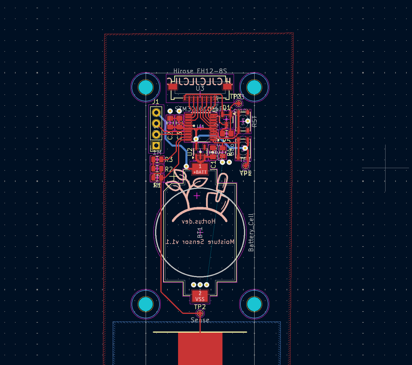 Designing the PCB in KiCad
The circuit itself is pretty simple. I have an STM32 microcontroller which has a pin connected to the capacitive sensing element via a few large resistors. This is used to charge up the sensing element (which is just a big copper area on a spike that is stuck into the soil) slowly enough that I can time how long it takes to cross a voltage threshold. This is measured by another pin on the microcontroller. There is also some voltage regulation circuitry, a serial port, and a bunch of pins broken out so that I can use them to drive the display.
I wanted to experiment with an STM32 as an alternative to the Atmel AVR chips that I normally use for my projects. After my social battery pin badges, one of the main draws for me was the fact that STM32s come preloaded with a bootloader that allows them to be programmed over serial out of the factory. It’s not the fastest way to get code onto them but it is quite convenient and requires less pins than an AVR ISP. Breaking out the SWD pins would be the ‘proper’ way to program this but it requires extra hardware which I didn’t have (at the time) and the accessibility of serial appealed to me.
The exact chip I chose was the STM32l010F4. At the time of design this was the cheapest, lowest power offering I could find in STM’s line-up. It has an Arm Cortex M0+ core which is made for ultra low power devices - very handy given that I want to run this sensor off of a coin cell! In order to get the most out of the coin cell I regulate the voltage down from 3v to 1.8v using an LDO. Initially I was planning to use a switching regulator as these are generally more efficient, but when working at these voltages and currents the difference in power consumption is actually pretty negligible and, for me at least, the low cost and low part counts needed for an LDO is worth the minuscule loss in power efficiency.
The last piece of the puzzle is the display which is pretty simple to drive. It has one common electrode and one electrode for each segment of the display. Segments are turned on and off by applying a positive or negative voltage to them relative to the common electrode. The display is relatively delicate so in order to maximise its lifetime the driving voltage should ideally be about 1.5v. The datasheet Ynvisible provides has a number of suggested driving circuits for creating this voltage, but I decided to use a pair of Schottky diodes in conveniently packaged together in the BAS70-04. These are arranged in opposite directions which means that I can use them to drop the voltage to a suitable level at the common electrode whether I’m driving the display forwards or backwards. I’m sure it’s not the best way but it’s low effort and it works! The display itself is semi-bistable which means that it maintains its state for a short amount of time even without power. Ynvisible suggest that it should be refreshed every 2 minutes or so to maintain a persistent image but I’ve had perfectly fine results leaving it as long as 15 minutes.
Software and testing
The software is written in C using the standard STM32 HAL libraries. I configured the internal clock to briefly wake the chip from deep sleep every 15 minutes (although this can vary quite a bit with temperature, and seems to tend on the shorter side - not too much of a problem in this case though). It takes a handful of measurements, averages them to minimise noise and updates the display with the new reading before going back to sleep. One issue with my method of taking measurements is that it’s never going to be that precise or accurate unless you can account for the exact composition of the soil, it’s density, temperature, etc… and even if you could control for that, with only seven bars on the display there’s a limit to the amount of detailed information that can be conveyed. I make up for these shortcomings by letting the user configure the high and low relative humidity levels shown for their particular plant through software. There is a button hooked up to an interrupt and with a little bit of fiddly code to detect single, double, and long presses. This lets them set own preferred levels on the display to suit their plant.
With the code loaded onto the device it was time to test it. I used a glass of water to check the basic functionality and confirmed everything was working. One of my original aims for the project was to make something that would last a long time on a single coin cell. I have a Nordic Semi Power Profiler Kit II which is a great little tool for measuring extremely low power devices. I hooked it up and let it record the power usage for an hour. It went through 4 measurement cycles as expected and averaged 10.3uA. With a 225mAh CR2032 coin cell it should last almost 2.5 years! not bad at all!
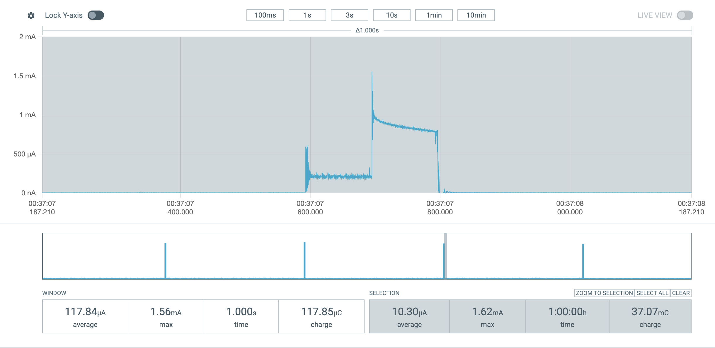 Measuring power consumption with the PPK II
Conclusion
It’s actually been a few months since I made the first board and I’m pleased to say that my plant is not just alive but thriving! I’ve since made more to keep an eye on the various plants around the house and I have a few up for sale on my store hortus.dev if anyone else is interested in getting their hands on one. I’ve also made a 3D printed cover that attaches onto the front of the board to make it look a little tidier (and prevents the reset button from being pressed, as it is only really needed for programming). Overall I’m really happy with how this project turned out - it’s probably the most useful thing I’ve made in a while and I’m particularly pleased with just how little power it uses!
