Simulating a glowing fireplace with an RP2040
If you want one of these for yourself, I’ve got a limited number available on my store: hortus.dev/products/fire-string.
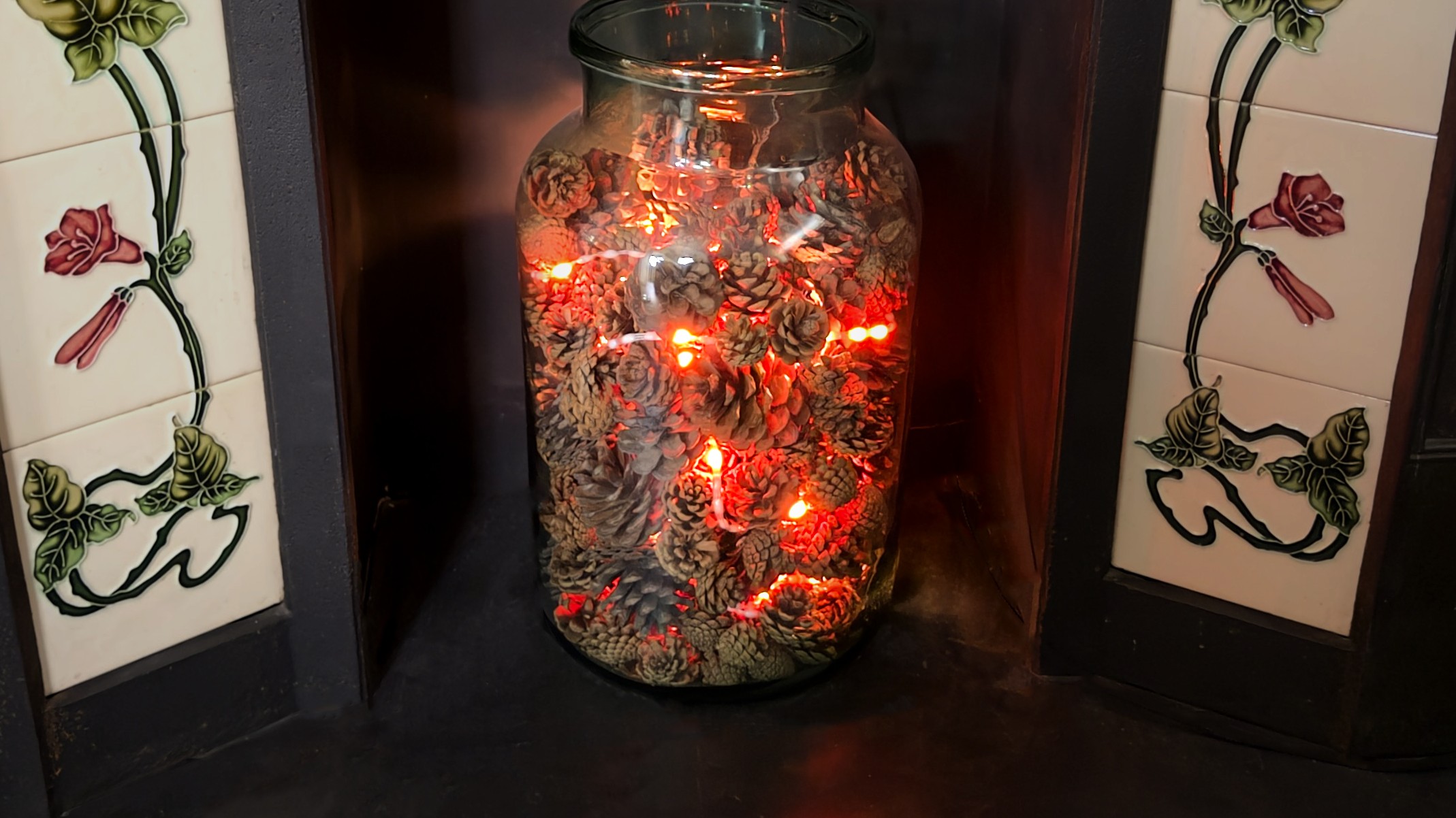
Like many houses in the UK, mine has an old fireplace that can’t be used. The previous owners blocked up the chimney and replaced the fire with an imitation electric one. I imagine they had perfectly understandable reasons for doing this, maybe they struggled with maintaining it or they were worried about safety with small children or pets around. From my perspective though, I always think these heaters are a poor substitute for the real thing. I’ve yet to come across one that doesn’t remind me that it would be much nicer if there was a real fire roaring in the hearth. As a result, the cheap electric heater that came with the house quickly made its way to gumtree so that someone who might appreciate it more could put it to good use. This left my partner and me with a slightly sad looking void in our living room. Over the years we’ve tried to fill it with various things like pots, plants and most recently a large glass jar. They looked nice, but always slightly out of place and they never did much to restore the coziness that I missed from having a real fire - specifically that relaxed feeling as you let the dancing embers hypnotise you as the fire burns down late in the evening. This felt like something I could capture with a microcontroller, a string of RGB LEDs, and a couple of free evenings.
The Theory
I love writing little simulations of physical things. There’s something satisfying about taking a real physical process, stripping it down to its core ideas, and seeing how far a few simple rules will get you. This project is very much in that spirit - it was inspired by the way that heat diffuses through and radiates away from objects as visible light, though as you’ll see there are a lot of big simplifications along the way.
The basic idea is simple: All objects emit light when they get hot. The hotter something is, the more it glows towards the blue end of the spectrum, and the cooler it is the more it glows towards the red end. There is a very specific relationship between temperature and colour. We call it black-body radiation and it is governed by something called Planck’s law. We, however, are not going to worry about that too much as for our purposes we don’t need to be physically accurate - we just need something that looks nice. We can get away with mapping some imaginary temperatures to a colour gradient that gives a satisfying effect. All you need to know is that we’re going to make the LED pixels in our string white when we want them to look really hot, red when we want them to look cooler, and yellow/orange for the temperatures in-between.
Try adjusting the temperature slider on the right to see how the wavelengths of light that are emitted change. Low temperatures emit light that only covers the red end of the visible spectrum, but as it gets hotter the peak shifts towards blue and we see a bigger range of wavelengths emitted across the visible spectrum which we perceive as white.
Black-body radiation isn’t just about colour, it also represents heat leaving a system. In a real physical system some heat is lost as radiation (the light that gets emitted by hot objects as previously discussed) and some is lost through conduction to whatever substance surrounds the object. We’re not going to bother modelling heat loss to radiation, but we can simulate heat being conducted away to the air very easily by just saying that each pixel always loses some small proportion of its heat. This will enable our LEDs to go from white to red and eventually fade to black as they cool.
This by itself wouldn’t make for a particularly interesting effect though. We need one last concept: some way for the temperature of pixels to change and for heat to spread through the pixels. To do that we introduce diffusion of thermal energy from hotter areas to cooler areas. This is governed by the heat equation, but again we can skip over and simplify this by going with the idea that every pixel will move some proportion of its heat to its neighbours. With all that in place we’ve got the foundations we need to code this up and start building our simulation.
Click or drag on the grid to add heat, then watch it spread and fade. Decay controls how quickly each pixel loses heat. Diffusion controls how much heat spreads to neighbouring pixels each frame. Try setting decay to zero and watch how heat diffuses outward until the whole grid settles to a uniform temperature.
Making it work
Rummaging around in my parts box I picked out a Pimoroni Tiny 2040 board and a nice long string of WS2812B LEDs that I’d been saving for a rainy day project just like this one. Hooking them up was as simple as connecting power, ground and data directly to the Tiny 2040. WS2812B led string like the one I used can draw quite a lot of power so it is worth thinking about how you are going to supply them. In this case however these concerns were mitigated by the fact that most of the LEDs would be lit as a low red with only the occasional bright white ember.
I initially implemented the code using circuit python mostly out of convenience. There’s something satisfying about being able to write code directly on the device and getting real time feedback as you make changes. The LED string was represented using an array. I implemented the ember effect by first adding heat to random positions in the array every frame, and then iterating through it applying the rules for decay and diffusion to each element and its neighbours. I then used a lookup table to render the correct colour values for the resulting temperatures in the array to the LED string.
Heat is randomly added to pixels each frame, then decay and diffusion are applied to produce flowing waves of colour. Each row is a continuous strip of LEDs, just like the physical string.
This produced a good effect, but it wasn’t quite what I was after. The string lit up in waves of red and yellow which was very nice, but it was a bit too continuous. I wanted little pinpricks of light that weren’t entirely connected, but still ebbed and glowed in roughly the same areas, as I thought this would produce a more convincing ember effect. Luckily this was pretty easy to do - I simply updated my simulation to skip positions in the array, which split and spread the flowing waves of heat across the string more.
The circuit python implementation turned out to be good enough that it’s been running in our living room for the last couple of months. The real measure of success though is that my wife has started turning it on unprompted - which tells me it’s actually doing its job. There are still some problems though. I was very lazy with my connections for the led string - just twisting and looping the wires through the holes in the Tiny 2040 without any solder. This works fine as long as no one touches it. If the USB cable gets jogged it can make the whole string cut out, flicker, or even burst into a rainbow of colours which isn’t really conducive to the warm relaxing vibe I’m going for. With that in mind, and the confidence that we would actually continue to use it I felt it was time to productionise things.
Making it nice
I wanted to start by designing a custom board around the RP2040. I hadn’t worked with it before beyond using random dev boards, and I was intrigued to see what it would be like to integrate into one of my own products. Potentially earning it (and maybe later its bigger brother, the RP2350) a permanent place on my roster of go-to chips. I probably could have got away with continuing to use an off-the-shelf dev board but there’s something satisfying about owning the end-to-end design and I’m never one to pass up an opportunity to learn something new.
I followed the reference design from the official raspberry pi RP2040 hardware design guide pretty closely, adding a 3 pin JST-XH connector for the LED string and a USB-C connector for charging and programming (it annoys me that the official pi pico boards still use usb micro connectors, as it’s one more type of cable that I have to keep around). The RP2040 needs more supporting hardware than I am used to. The nature of my projects so far have meant that I tend to get away without an external crystal or flash but both are required for the RP2040. It also has slightly more interesting power supply requirements, needing both a 3.3v supply and a 1.1v supply (which can be generated by an internal LDO, but still requires traces between pins). This is something I somehow missed when designing the first revision of the board, resulting in some very hot, very broken chips when I plugged them in. I had managed to connect the 3.3v supply to the output of the 1.1v LDO. Unfortunately the relevant traces were all hidden under the chip which made a bodge-fix impractical. This was annoying, but mistakes happen and I learned a while ago not to beat myself up too much about it! Whenever I design new hardware I always anticipate and budget for a couple of revisions on the basis that I won’t get things perfectly right on the first shot, but thankfully with time and experience silly mistakes of this magnitude are becoming pretty rare for me.
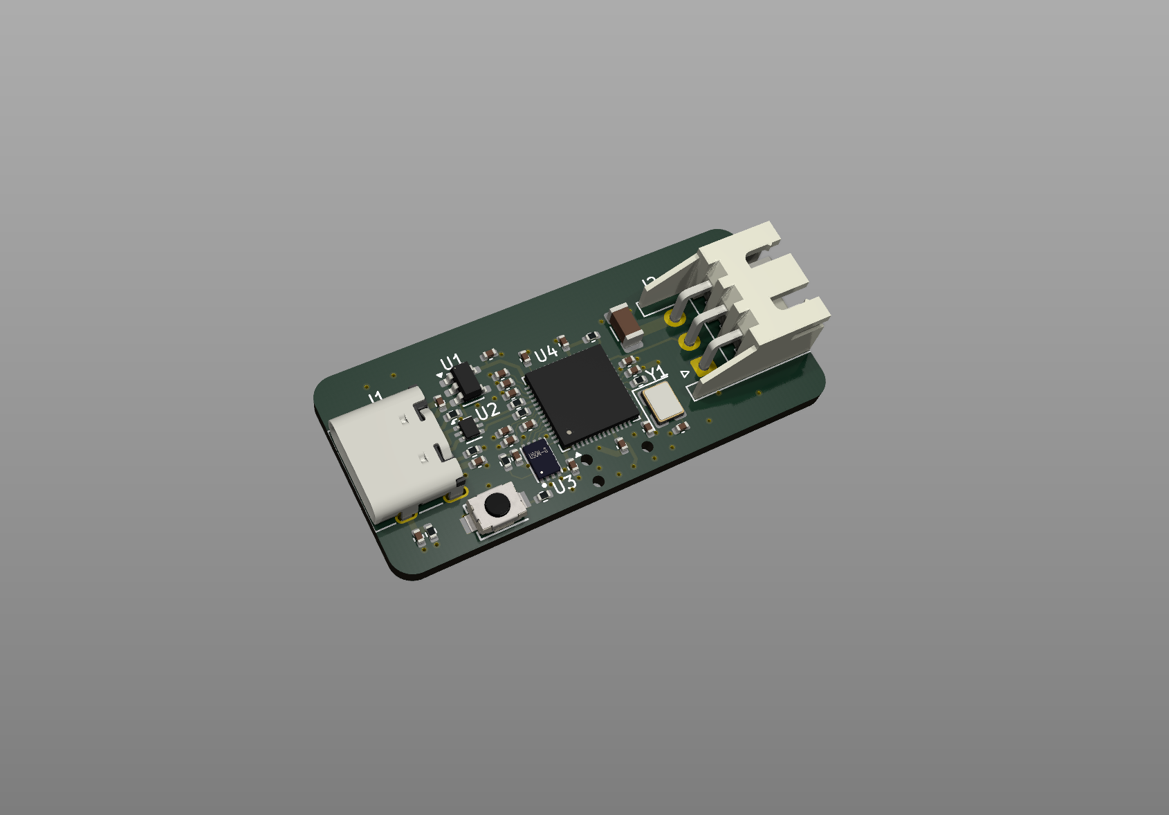 3D render of the custom RP2040 board from KiCad
Happily the second revision of my boards worked flawlessly, which meant it was time to focus on firmware improvements. My original firmware worked well, but I was aware that it wasn’t particularly well optimised which was limiting the frame rate to about 10 frames per second. That in turn meant that there wasn’t much headroom available to further tune and improve the ember effect, or experiment with new approaches. I broke out Claude Code to help me with this. I’m aware that for some people reading, the use of AI might be a bit of a turn off, but for me it has vastly expanded my ability to execute and finish projects and ideas. I am as concerned as anyone about the rise of AI slop, but I strongly believe that these tools offer huge amounts of value and potential when wielded intentionally. For me, that means delegating implementation (especially when it is tedious or repetitive) but not decision making, and also using it to fill the gaps of my knowledge and experience, but not going beyond it. I still love writing code for its own sake, and I don’t think being good at it stops mattering - if anything it matters more, because it’s what lets you make good decisions about what to delegate and what to keep. For me the sweet spot is building out a solid skeleton of an idea myself and using AI to help flesh it out without needing to be an expert in everything. It lets me move faster without losing the thread of what I’m actually trying to build.
Claude helped me go from 10 frames a second up to about 80. The biggest win was porting from Circuit Python to Micro Python so that we could take advantage of the @micropython.viper annotation which lets us compile our code down to machine code at runtime. This allowed us to write colour values for each LED directly into memory, bypassing all the usual Python bookkeeping. Without it, Python was doing a lot of invisible work behind the scenes for every single LED, on every single frame which adds up quickly over 300 LEDs. This optimisation got us around a 3x speedup. The next biggest win was converting all of the floating point maths to integer maths. Floating point is how computers typically handle decimal numbers, but the RP2040 has no dedicated hardware for it - every calculation has to be emulated in software, which is slow. By scaling everything up to work with whole numbers instead, we cut that overhead entirely and got another 2x speedup.
Having reclaimed a significant amount of processor time I was able to really go to town on the effect and experiment with tuning it. The first thing I did was change the way heat got added to the system. Instead of randomly adding it directly to the pixel array, I introduced the concept of fuel by creating a second array, and slowly transferring heat from this to the pixel array via a burn rate parameter. This meant that hot pixels would ramp up in their brightness rather than instantly lighting up. Next I changed the diffusion, decay and burn rate parameters as well as the probability of fuel being added to use look up tables based on the current temperature of the pixel they were being applied to. This meant that instead of every pixel behaving the same way regardless of how hot it was, each pixel could follow its own curve. A cool pixel might decay slowly and be quick to reignite, while a hot pixel might shed heat rapidly - mimicking the way real embers behave differently at different stages of burning. This gave the effect a much more organic, unpredictable feel, with most pixels settling into a deep red glow but occasional flares punching all the way through to white hot before fading back down.
This is the actual simulation running in real time using the same algorithm as the firmware. Fuel is randomly added to pixels and slowly converted to heat via a burn rate, which is why embers ramp up gradually rather than appearing instantly. Each parameter varies with temperature - cool pixels decay slowly and reignite easily, while hot pixels shed heat rapidly.
With so many parameters to tune, it was becoming quite tedious to make changes as I had to update and upload the code every time I wanted to tweak something. To make life easier I made a HTML/JavaScript based configurator that let me design the various curves graphically and have them update on the LEDs in real time by sending the parameters to the board via the Web Serial API. This was quite fun to play with but I found that it was very easy to lose track of the settings that I liked while I fiddled, so I added functionality to save and load presets.
With the electronics and firmware in a good place, the last thing to do was give it a proper home. I modelled an enclosure in Onshape, designing it as a two-piece shell with curved edges so the top and bottom mate together cleanly. I added internal snap clips so it holds together without any screws or glue, and had it 3D printed. The final result looks really polished and gives the whole thing a much more finished feel.
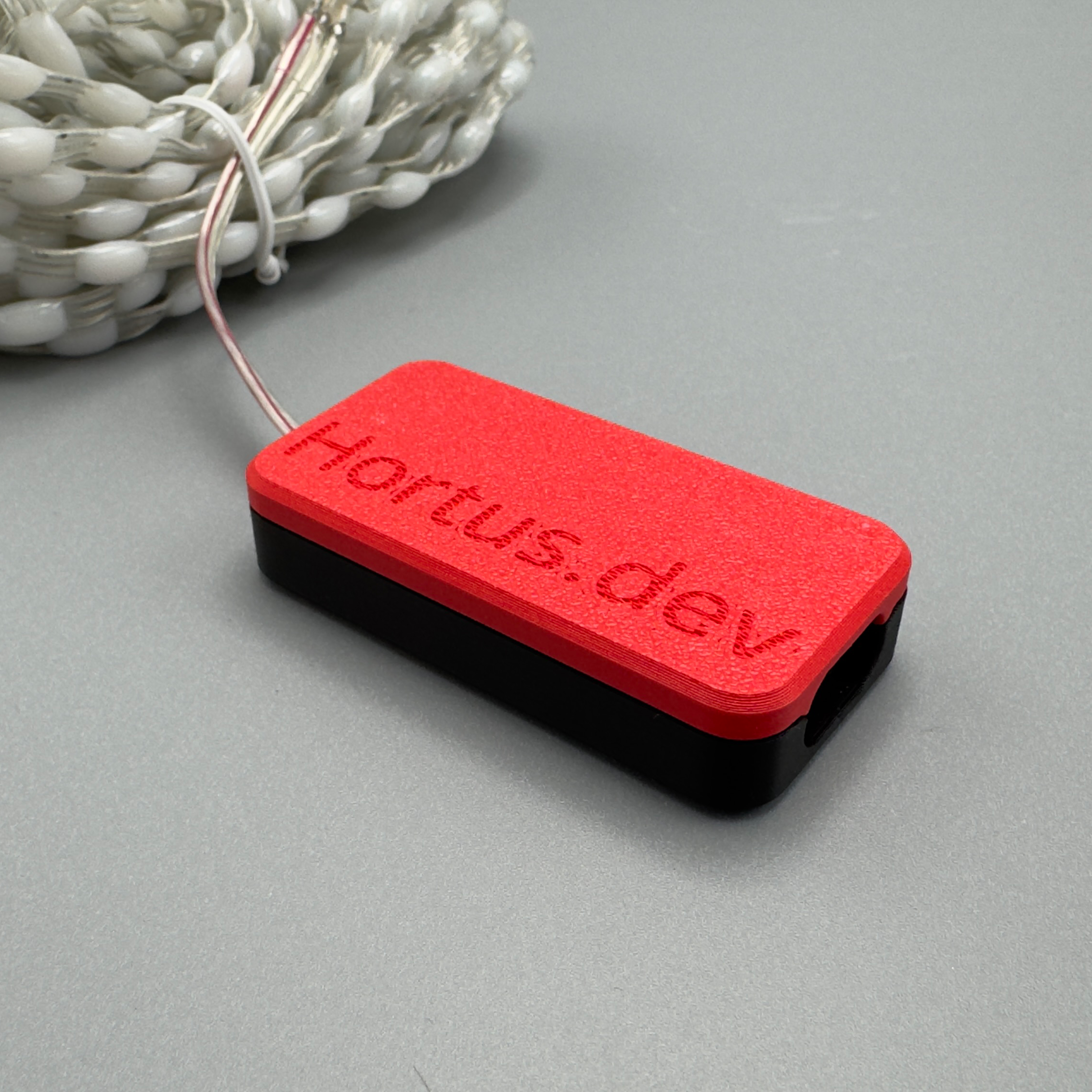 The finished board in its 3D printed enclosure
What started as a tangle of unsoldered wires has ended up as something I’m genuinely proud of. The project has a custom board, firmware that runs well, and a configuration interface that lets me dial in exactly the effect I want. The whole thing feels complete and more importantly it’s still sitting in our fireplace doing its job every evening.
Making it your own
I had a great time working on this project, and if you want a share in some of the joy I derived from it the code and files are available on GitHub. That repo contains everything you need to build your own version of what I’m calling the ‘Fire String’ either by getting your own boards made or doing something similar to my early prototype version with an off-the-shelf RP2040 dev board like the Raspberry Pi Pico. Alternatively if you just want a complete polished product in your hands like the one I ended up with I’ve got a limited number available for sale on my store at hortus.dev/products/fire-string along with a bunch of other projects that I have worked on.
